
For the 115V and 230V EU Internal Non-Redundant test bench, the Yokogawa WT5000E is employed to monitor and measure various input parameters, including input voltage (V), input current (A), input frequency (Hz), input power (Watts), power factor (λ), and input current total harmonic distortion (THD %)
Figure 5 below is Yokogawa WT5000. It monitors the input parameters with no filters applied to the power analyzer. An exponential average rate of 32 samples is enabled with a refresh rate of 200 milliseconds. A 1-Phase 2-Wire wiring configuration is used, with the voltage and current range set to Auto and the measuring mode set to RMS. The instrument is set in normal measurement mode for harmonics measurements, with a maximum order set to 50 using the IEC formula, 1/Total.
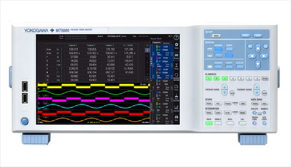 Figure 5: Yokogawa WT5000 Power Analyzer | 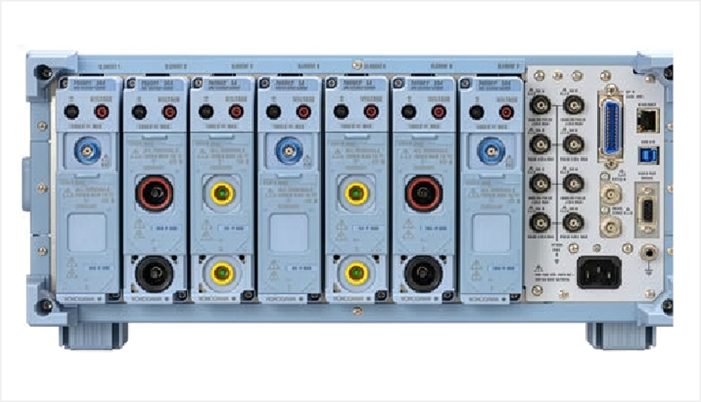 Figure 5: Yokogawa WT5000 Power Analyzer |
In the context of the 115V and 230V EU Internal Non-Redundant test bench, the monitoring and measurement of output parameters are carried out using the Chroma 63640-150-60 and 63610-80-20 DC load banks shown in Figure 6. These measurements are taken at 1 second interval during the 15-minute interval per load set point. The recorded parameters encompass output voltage (V), output current (A), and output power (Watts).
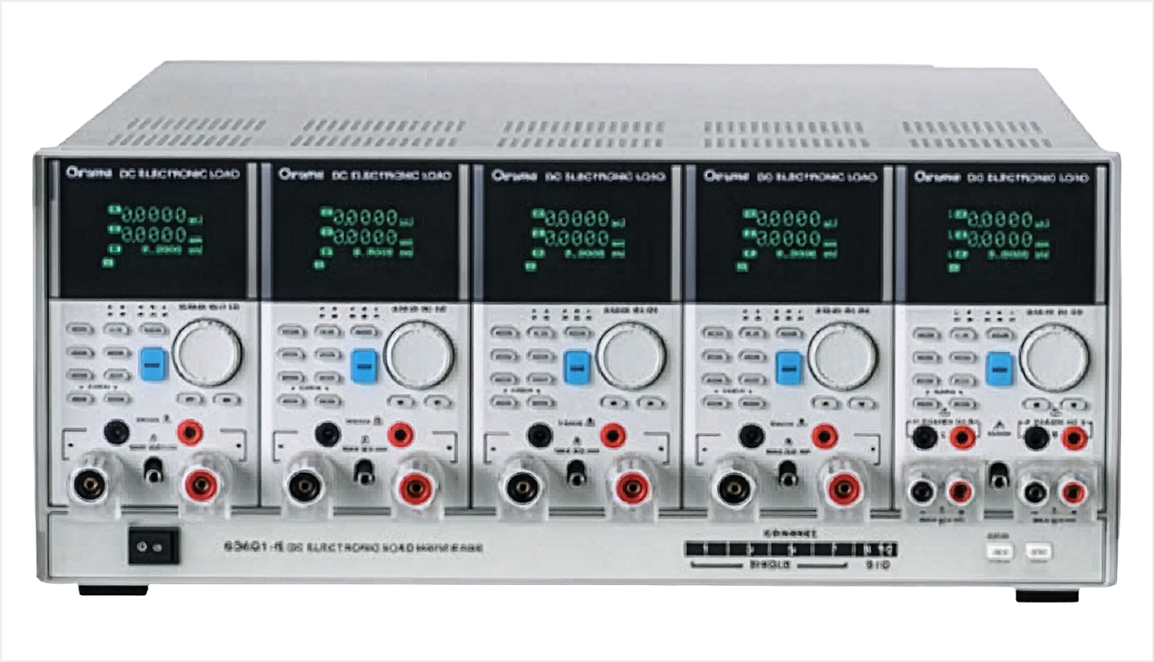 Figure 6: Chroma 63640-150-60 & 63610-80-20 DC Load Banks |
230V, 277/480V, and 380V DC Internal Redundant power supply; the Hioki PW6001-16 monitors and measures a range of input parameters. These parameters encompass input voltage (V), input current (A), input frequency (Hz), input power (Watts), power factor (λ), and input current total harmonic distortion (THD %). Additionally, it is used to monitor output and external fan parameters, including voltage (V), current (A), and output power (Watts).
Specifically, for the 230V Internal Redundant, 115V Industrial, and 380V DC test benches, the Hioki PW6001 is employed. Filters are not applied to the power analyzer, and data recorded rate is set to 200 milliseconds. The wiring configuration is 1-Phase 2-Wire, with voltage and current ranges set to Autoscale. The measuring mode is RMS for the AC Input channel and DC mode for the DC output channels. For harmonics, the maximum order is configured to 50 using the IEC formula 1/Total.
Regarding output current measurement for the test bench, Hioki current transformers are actively used, as depicted in Figure 7. The selection of current transformers depends on the maximum rated current of the power supply rail, which can be 20A, 50A, 200A, 500A, or 1000A. Before each test, each current transformer undergoes demagnetization and zero adjustment.
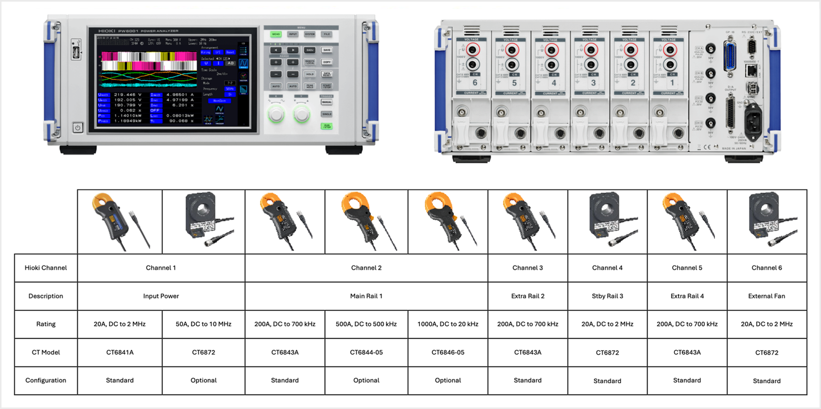 Figure 7: Hioki PW6001-16 Power Analyzer and Current Transformer Sensors |