
To accurately measure output voltage for desktop power supplies tested at both 115V and 230V EU input, we connect sense leads from the Chroma 63640-150-60 and 63610-80-20 electronic load banks directly to the rear of the output connectors using piercing probes. These probes interface with the back of the cable connector that connects to the load, ensuring voltage is measured as close to the load input as possible. Measurements are logged every second during the 15 minute steady-state period for each load condition. Figure 3 below shows an example of a single probe placement of a connector and highlights the monitoring points noted on the test board.
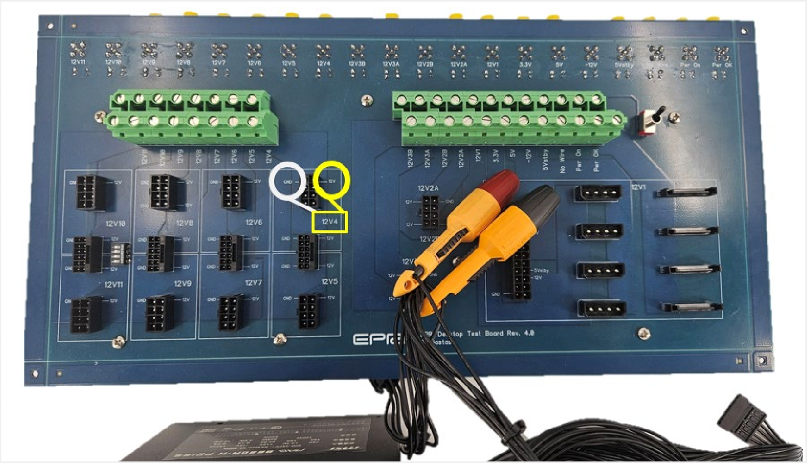 Figure 3: Insulated Piercing Probe to Measure the Multi-Output Voltages of Desktop Power Supply |
The same procedure is followed for 230V & 277V Internal Redundant, 115V Industrial, and 380V DC test power supplies unless a custom interface board is supplied with the unit. If a custom interface board is provided, test points must be incorporated to measure the output voltage and return ground directly when they exit the mating connector on the load side of the unit. Test points should be marked on the test board or in photos accompanying the submitted units, as shown in Figure 4.
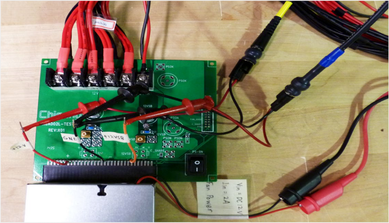 Figure 4: Sense Line, when provided, is used to measure the output voltages |